“Wire” is a Funny Word in the South
I’ll spare you the boredom of installing motherboard headers. If you’re following these steps, it’s doubtless that you’ve suffered through the miniature hell that is comprised of front panel connectors. Always check the +/- orientation for the LEDs; if you don’t do this, your activity lights won’t work correctly.
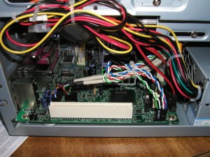
Also, I realize I pointed this out on the previous page, but make absolutely certain you install the components in the order of: motherboard, hard disk, optical drive. Here’s what it’ll look like with all three installed and cabling completed:
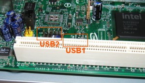
I have a few more pictures, but I think there are a few noteworthy issues with this particular motherboard that should be briefly discussed before we finish up. First, there are two USB headers (internal) for front panel use. This would ordinarily give you a total of 4 front panel USB connectors but most cases only provide two. Naturally, this means you’re only going to be using one of the headers. Unfortunately, the USB1 header is located right against a capacitor and the PCI slot. The picture above isn’t a very good one, and I don’t have a great shot of the header in question. So, let’s resort to one of my prior shots of the motherboard:
USB2 is actually located much farther away from the PCI slot than this image suggests. The yellow header to USB2’s right is the HD audio front panel header (I had no issues with it). USB1 is located IMMEDIATELY behind the PCI connector somewhere inside the superimposed orange square. If you can see the top of the blue capacitor in USB2’s box you can roughly estimate the location of USB1 by simply moving a couple of millimeters to the right.
Ordinarily, this wouldn’t be a problem, but I had to reroute some wiring and removing the front panel USB header from USB1 was a total pain in the neck. There isn’t any room to get your fingers around either side of the connector, and I’m really glad I didn’t slide it in all the way. I would’ve never gotten it out. Intel deserves a slight smack on the wrist for this.
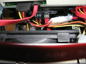
Next up, here’s a shot of the hard drive mount point. It’s located in a slightly recessed tray directly beneath the optical drive and about an inch and a half above the PSU.
It’s a tight fit. Here’s a shot of the connector side of both the optical drive and the hard disk:
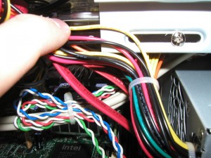
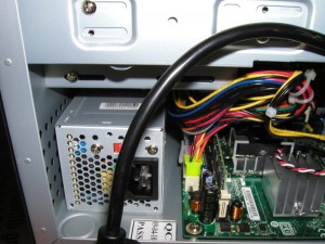
Since you’ll be reinstalling the PSU, there’s on minor detail that you don’t want to forget:
See that dangling cable? The PSU must be plugged in inside the case, too.
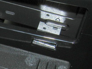
With that, we’ll reinstall the case cover and take a look at the finished product. There’s one other modification I had to make.



2 Responses to “Atom-based Media Center: Part 1”
Took me awhile to get around to reading this but very informative! Your shopping list of hardware and the picture examples were a lot better than some of the sites I read on the topic of mythtv type boxes and hardware. It helps to have visual examples and it’s too bad a lot of pages dont seem to be very creative in that sense. I look forward to seeing the next part about the software.
I’ve started saving up to get some of the hardware so this way I can start building sooner rather than later.
One thing I think I didn’t stress much in the article is that the Intel 945-based boards are a little under powered (or feel that way). The NVIDIA Ion systems might be a bit more appropriate, but I haven’t found one that has a decent expansion option! I’m hoping this will change. All things considered, though, the Atom 330 + i945 is a pretty decent mix for a basic HTPC. It probably won’t do HD well and flash movies are a little jerky (maybe it’s just the Youtube videos–some of them are pretty awful quality-wise).
If you want something a little more powerful, there’s a lot of mini-ATX boards out there that support Core 2 systems–I even found one by SuperMicro that’s based on the Atom. Though, one thing about the Core boxes–they can’t beat the Atom when it comes to power consumption. I think the processor idles at about 8 watts.
Leave a comment